Fundamentals of Isometric Pixel Art
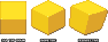
In pixel art, "isometric" refers to work which utilizes the graphical projection of isometry rather than traditional (also known as linear) perspective. While all forms of perspective require at least one vanishing point, isometric pixel art has no vanishing points. Because of this, the foreshortening (reduction in visual length of something as it recedes into space) is equal on all surfaces and is not dependent on the distance from the viewer. This makes isometric projection a good option for things like architectural and technical illustration as well as game art. In an isometric view, the width, depth, and height of a cube are all equal measurements visually. Two side faces of an object are visible as well as its top face, which creates the illusion of an overhead view while allowing for greater detail description and immersion than the somewhat similar ¾ top down ("zelda-like") view or a side scrolling/platformer perspective.
While an isometric view requires more faces of an object to be drawn, the trade off is that freely movable objects like characters actually need fewer unique sprites to represent them in all necessary orientations. A ¾ top down game requires animations of the side, top, and bottom views, but, if the character is symmetrical, an isometric game only requires the two diagonal front and back views. Even if the character is not symmetrical, you may still want to use mirrored versions, as the additional workload of creating unique animations for all four directions is often not justifiable. An isometric view is suitable for games which require movement along all axes, although, like ¾ top down, the comprehension of vertical distance from the ground plane may be reduced. Isometric (sometimes shortened to "iso") pixel art has a particular artistic quality that many find charming, cozy, or nostalgic, and it is also a great choice for non-game related art with a focus on interior or exterior environments (rather than characters.)
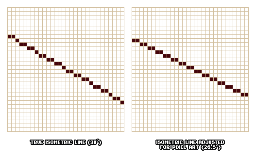
The 2:1 (2x,1y) line is the foundation of isometric pixel art. All lines parallel to the ground plane which are aligned to the isometric grid (i.e. not rotated) will utilize this line pattern. It’s worth noting that this is actually an approximation of true isometry (26.5 degrees rather than the mathematically accurate 30,) but the line pattern is much more conducive to pixel art than the pattern a true 30 degree line creates. As in any type of pixel art, you must always be aware of the minimum required pixels for any element in your sprite and make design choices with this in mind. With a typically-sized sprite for game-esque graphics, because of the 2:1 line pattern, a single pixel can make a huge difference, particularly when it comes to the depth of basic forms comprising a larger object and the way aspects of an object align. In order to accurately convey certain proportions of some objects, you may find yourself having to make an object smaller or larger than originally intended. The fewer pixels you have available, the less granularity you have regarding design choices.
Graphical projections and traditional perspective are mutually exclusive, but you may choose to add a bit of expansion and contraction to your objects to make things less rigid or to approximate some sense of perspective. These elements are more difficult or impossible to tile and this technique should be used with discretion.
Constructing Objects in Iso
You may be able to approximate an isometric view in a freehand sketch, but construction lines, which are used for measuring but will ultimately be removed or filled in, are necessary in order to create accurate and visually consistent objects. Because there are no vanishing points and surfaces are equally foreshortened in this view, it is much easier to measure the lengths of faces and to make sure proportions are as intended. Organic forms and structures can be contained in isometric boxes to ensure they don’t look out of place against more manufactured objects.
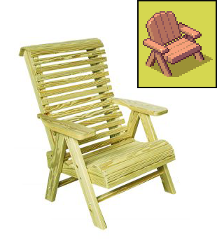
Here's an isometric pixel scene I worked on recently as a mockup for a game. To illustrate how measuring and construction lines can be used to create basic shapes which make up more complex isometric objects, let’s go through the steps of creating one element of it (a wooden chair.)
Before I begin, I look at some reference photos of similar objects and examine the proportions. I notice that the chair can be split roughly into vertical thirds. You will most likely have to simplify and reduce various types of detail in your iso sprites (namely small and repeated elements like planks, slats, and tiles,) so it is wise to consider these design simplifications at the beginning of the process. For this sprite I am altering and simplifying many aspects of the design and I know I will need to reduce the number of slats significantly. I'm making the chair more squat overall to give a "cuter" effect and better match with the style.
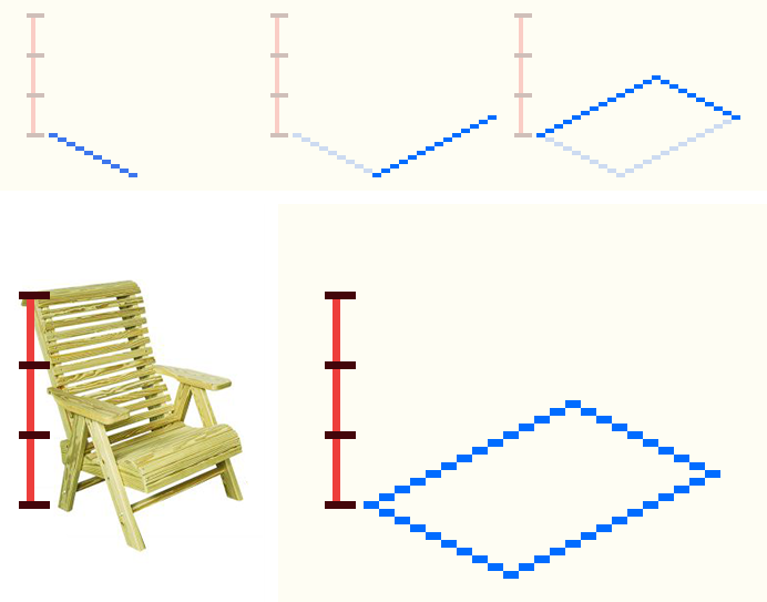
1. Roughly draw out the footprint of the object to your desired scale and size. Measure and mark out important design landmarks. Using the rectangular marquee tool and its associated info window is my preferred way of measuring in general.
Rectangular shapes are simple in iso. Just draw out the width and the depth, then duplicate and flip to form a rectangle.
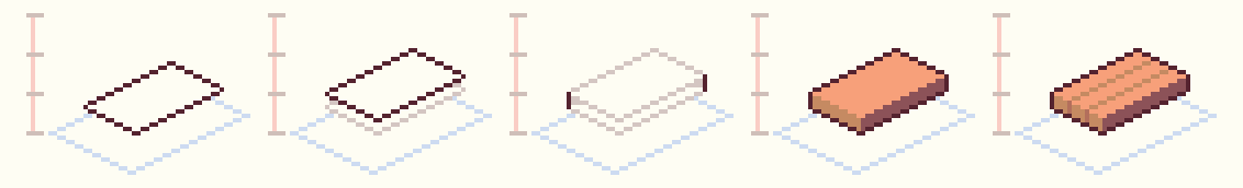
2. Draw out the basic foundational elements. You may choose to leave these elements as line drawings until the end of the process or you may want to do some basic shading at this point if you find that less visually confusing.
To create a rectangular form like the seat of the chair, draw a rectangle to the desired proportions. Duplicate this rectangle and slide up to the desired height, then connect the two rectangles with vertical lines.
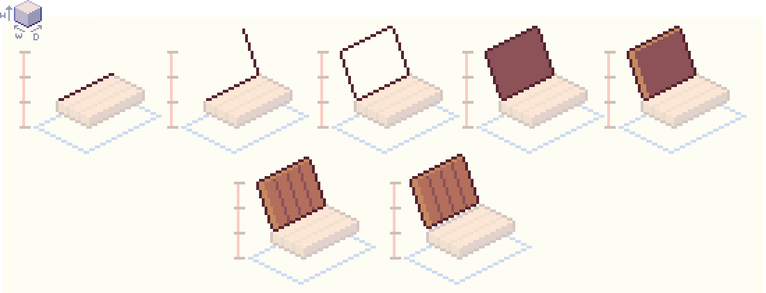
The back of the chair is, foundationally, just another rectangle, but vertically oriented and at a bit of a slant. I know I am going to need to split the back into several planks in a way that will fit within this rectangle but also facilitate an arched shape at the top. To do this I draw a rectangle that will make up the overall silhouette of the back (minus the arch) by drawing a 2:1 line that corresponds to the depth of the seat. Then, I draw a line to the desired height at the desired angle, then duplicate these lines and flip to finish the rectangle. I draw in a couple of pixels of dimension on the side edge and a bit along the top edge. I find a pattern that allows me to split the back into four planks, then I offset the back to the left and up a pixel to remedy the tangent caused by the back and seat overlapping and to create some negative space. We’ll leave it in this unfinished state until we construct the rest of the parts of the chair to ensure everything works together okay before spending too much time rendering detail.
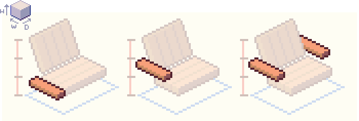
Create the arms by making a rectangular box similar to that of the seat, but thin and with less height and a little bit more width. Slide it up to the desired point on the chair and move it back along the 2:1 line pattern so that it connects with the back of the chair. Duplicate the arm and move along using the 2:1 line pattern to ensure it remains aligned to the grid. You may decide to un-align elements in order to achieve a certain effect and avoid things like tangents and weird overlaps, but make sure you’re not doing this accidentally as it may make the rest of the process more confusing.
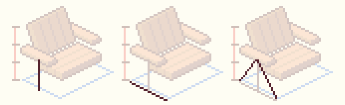
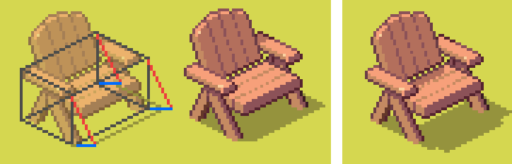
When drawing something that is angled (like the legs) the easiest way to approach this is to use construction lines to determine where an angle begins and ends or to find where two angles converge (and draw the lines connecting those points.) In this case, because the front and back of the legs are symmetrical, the easiest way is to draw a vertical center line down to the intended height. Extend construction lines of equal length out on both sides at the bottom of this line. Then, connect the ends of those lines to the point where they meet in the middle.
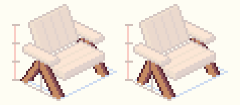
Replicate these angles a few pixels down to turn this line into a shape. Then, duplicate the shape and shift it 2 pixels to the right and 1 pixel up. Add outlines to connect the two shapes into one form. Duplicate the form and move along the 2:1 line pattern to align the back leg with the back arm. Make sure the legs are layered under the arms.
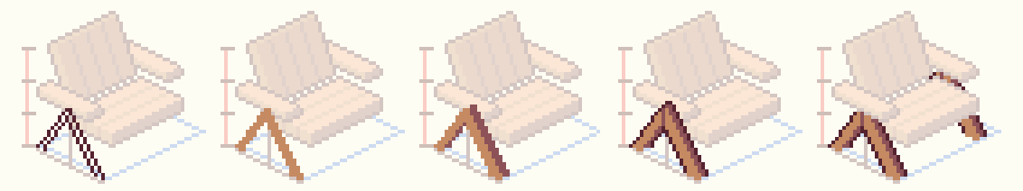
You may find that you need to adjust the angle of a line and/or the alignment and symmetry of shapes in order to achieve the effect you want. Although this may be less mathematically accurate, it is often worth it if it means you are able to use line patterns that are less jagged and easier to work with (like 1:2 pixel line.)
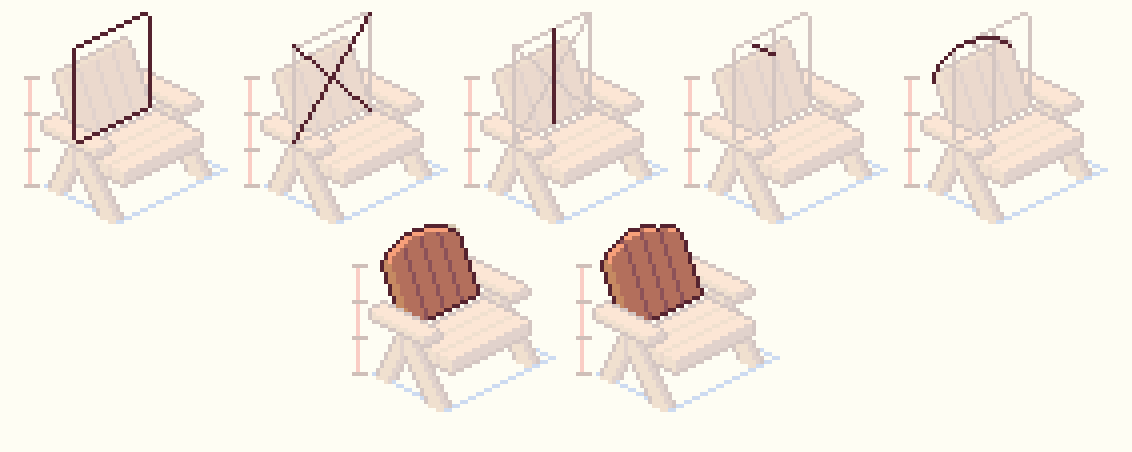
3. Render the details. Find the center of back of the chair to determine where the center and highest point of the arch will be. Finding the center of a box in an isometric projection is easier than if it were in perspective, since you can just count the pixels. However, you can also make an X between the corners of a rectangle and draw a line through the center of the X (this method works for both isometric and regular perspective drawings.)
Since the back of the chair is slightly tilted, I’ve used a 2:1 guideline to bring the center point back in space a bit. Also, since I know where the center of the back is at the bottom edge, I can just continue that line of the gap with two planks on either side up to find the peak of the arch. You may need to fiddle a bit with curved lines like this until it looks right to your eye.
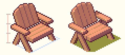
4. Polish. Adjust things as desired. Add squash and stretch at this point if you’d like. Refine shading and detail. Not only have I added specular highlights and cast shadows, but I’ve shaded the outlines according to the lighting as well. I ended up moving the back arms and legs to the right one pixel, and I rounded out some edges on the arms and seat.
Round, Rotated, and Organic Objects in Iso
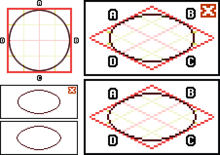
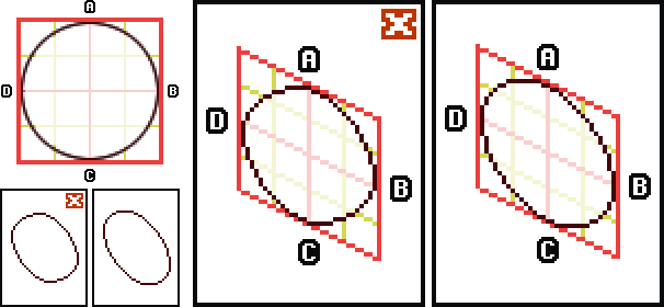
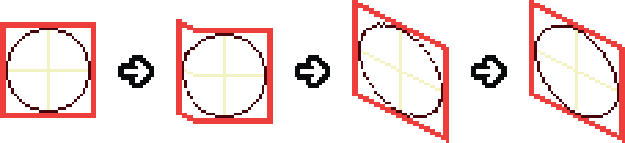
Drawing rounded isometric objects can be tricky—the majority of information about an ellipse is contained on the ends, also known as the vertices. This remains true in iso, so pay special attention to how you render those curves at the edges. You can contain ellipses in isometric square construction boxes to make sure the look stays consistent and that the outline hits the correct points.
If you’re really having trouble drawing something in iso, another thing you can try is to begin by drawing out the shape flat on the screen, as if you’re looking at it straight on. Then, slide segments of the shape up or down according to the 2:1 line pattern (or use the skew tool.) You will probably need to do some touch ups by hand, but it can be a good jumping off point for tricky details.
To help draw rotated shapes which are not aligned to the angle of the iso grid, you can also use this grid projection technique. Make sure that the corners of the shape hit at the correct points on the grid, and connect the points.
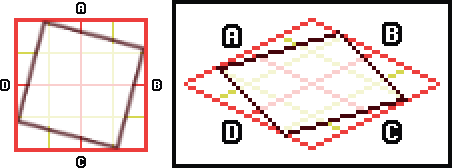
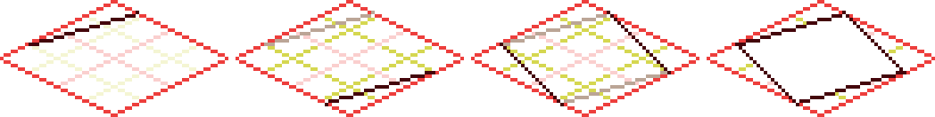
If you are drawing an angled square, you can also just draw an angled line that connects any two points on the perimeter of the isometric square, then duplicate it and flip both the line and the grid it is attached to horizontally and vertically and connect the edges of the two lines.
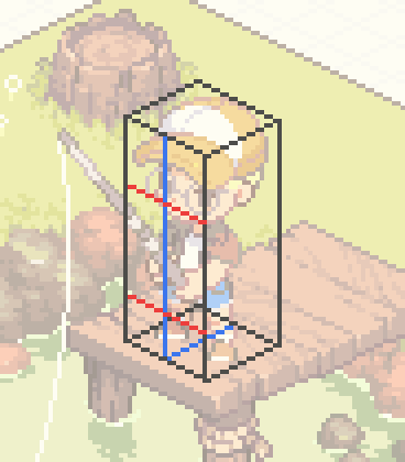
Some things, like characters and environmental details, may not be able to be created with construction lines, but you can still use basic isometric containers and measuring lines to ensure they conform to the qualities of the isometric projection overall.
Rendering Isometric Objects and Edge Definition
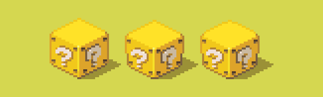
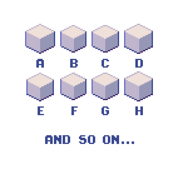
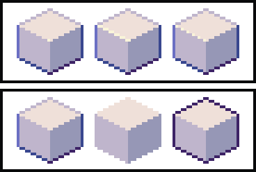
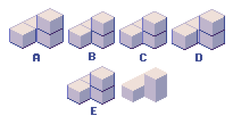
There is less room for creative or expressive linework in isometric pixel art, so the specific choices you make regarding edges and highlighting play a large role in the overall character of the work. There are actually many slightly different ways to render an iso cube, and while certain cubes stack and build on each other more naturally, if you are not utilizing tiled blocks in this way you may decide to alter the edge rendering in order to make a particular object appear more according to your taste and perception.
Although construction lines are crucial in the process of creating isometric objects, visible inner lines often ruin the illusion of dimensionality.

You can lighten or remove the outlines where the object connects with the ground plane or another surface in order to change the way the connection appears.
Because there are no vanishing points in an isometric scene, there is also no horizon or visible sky (unless the scene is self-contained and is intended to be above or within the atmosphere, in which case there may be sky below, but there will never be a horizon line.) Any sense of weather, time of day, or environmental conditions must be conveyed through other means, namely: the color palette, the position and nature of cast shadows, and the rendering of the scene overall.
Casting Shadows in Iso
Understanding how to determine the position of cast shadows in your drawings is an important skill, whether you are a traditional artist or a pixel artist. Because there is no horizon line (and, consequently, no shadow vanishing point) in an isometric projection, rendering cast shadows in isometric pixel art is slightly more simple, but I would highly recommend you get yourself accustomed to the technique in perspective so you will be more comfortable casting shadows in iso and in any other type of art.
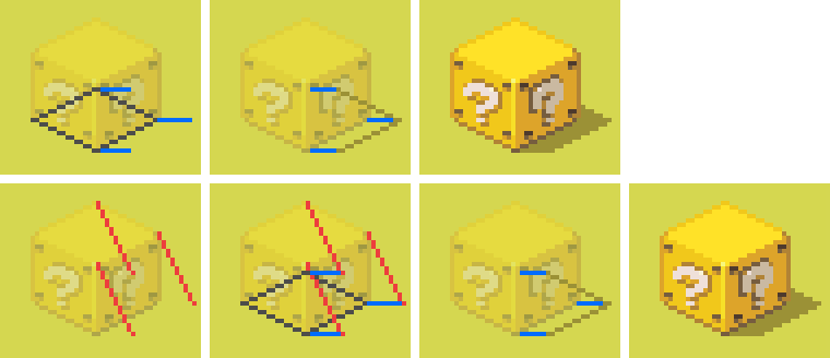
The easiest way to cast shadows on a flat plane in iso (of shapes that do not taper or can be approximated into a shape that does not taper) is to simply project lines from the bottom edges of the form at the same angle (of your choosing) along the ground plane. These lines should also be the same length as one another. The angle of these lines shows the direction of the light and length of these lines affects the theoretical angle of the light. Connect the end points of these lines to form the shape of the shadow. If you were to project lines from the top edges of the object to the ends of the first set of lines on the ground plane, you will notice that this second set of lines are also all the same angle and length to one another. If you would like to begin by determining the angle of the light source you may draw these lines first, but I usually start with the lines from the bottom edge so I know my shadow will not be longer or shorter than intended.
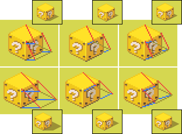
For most purposes, a light source which hits the top face mainly as well as one side face partially is most effective, as each face will have a different value, making it easier to read visually. A cast shadow running horizontally to the right or left is consistent with this lighting angle and tends to work well in iso as it aligns to the grid nicely. This type of lighting portrays most common real-world scenarios, like an outdoor scene with the sun shining above or an indoor scene with lights on the ceiling. Other lighting situations, like a backlight or a light shining more from the side are possible but tend to look less believable and are less visually readable.
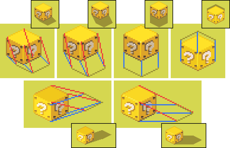
Casting shadows becomes more difficult when the shadow falls on something that is not just a flat surface and when an object is floating or has elements that do not connect with the ground plane. It is a good idea to brush up on how this technically works, but many times you may want to simplify the shadow an object casts by containing the object in an isometric box and casting the shadow according to that form.
More realistic doesn’t always = better. I chose not to have any cast shadows under the dock because I just didn't like the way it looked. Remember that, in isometric pixel art as in all other forms of art, even if something is technically "correct," if it just doesn’t look right you are always free to take creative liberties.
Subscribe to Pixel Parmesan
Get the latest posts delivered right to your inbox